
 Range image
Other Accessories
Compression Fittings
Brass compression fittings for 6 x 4 mm tubing, vibration resistant.
Part codeCompression Fittings
Review the available products and specifications. Our team can help you select the right configuration.
Nozzles, tube fittings, pressure gauges and hoses.
Range imageOther Accessories
Brass compression fittings for 6 x 4 mm tubing, vibration resistant.
Range imageOther Accessories
Reinforced 180 bar discharge hose linking cylinder valve to manifold.
Range imageOther Accessories
Brass 360° flooding nozzle in four pipe sizes from 1" to 2".
Range imageOther Accessories
Stainless 90° kitchen nozzle, G¼" female, for wet chemical lines.
Range imageOther Accessories
Stainless 60° spray nozzle, G¼" male, for targeted local discharge.
Range imageOther Accessories
Stainless 90° wide-mouth nozzle, G¼" male, for broader coverage.
Range imageOther Accessories
0–100 bar stainless gauge, 40 mm dial, back entry.
Range imageOther Accessories
0–28 bar brass gauge, 23 mm dial, for low-pressure cylinders.
Range imageOther Accessories
0–350 bar mild steel gauge, 40 mm dial, bottom entry.
Range imageOther Accessories
Brass push-in fittings for 6 x 4 mm tubing, tool-free assembly.
Range imageOther Accessories
Reinforced 500 bar pilot hose carrying actuation pressure between cylinders.
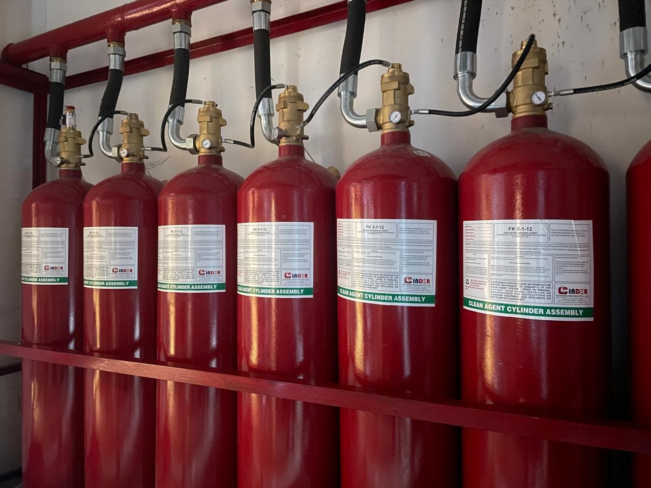
Installation accessories for suppression and flooding pipework: brass and stainless steel discharge nozzles, compression and push-in fittings for 6 x 4 mm tube, cylinder pressure gauges, and reinforced discharge and slave actuation hoses.
Accessories complete the detection, actuation and discharge networks. Nozzles distribute agent, fittings connect the specified tube, hoses serve particular discharge or pilot duties and gauges indicate pressure. Each item must match the role shown on the system drawing. Compare thread standards, materials, working limits and the connection arrangement rather than treating similar diameters as proof of interchangeability. Nozzle pattern alone does not establish protected coverage, and a gauge reading alone does not prove an entire system is ready. Include the existing equipment references and drawing when asking for replacements or quantities.
No. The angle describes the pattern, but coverage depends on the nozzle, agent, discharge conditions and approved layout. Ask for the model and orifice required by the system design.
No. It is one indication for inspection. Detection, actuation, control interfaces and the discharge path still require the checks specified for the system.
Tell us about the space you need to protect and an engineer will recommend the right system.
This range includes different spray patterns and connections. Ask the designer to confirm the required nozzle model, orifice and position for the selected agent and hazard. A quoted angle is not a coverage calculation, and connection size alone does not determine discharge performance. Confirm the arrangement after equipment or room layouts change.
Check the exact thread standard, material, working limits and available bend or installation space. The catalogue separates discharge hoses from slave or pilot hoses because their duties differ. For tube fittings, confirm the tube dimensions and manufacturer-approved assembly method. Do not resolve an uncertain connection by forcing together similar-looking threads.
Select the required range, connection and mounting orientation for the monitored equipment. The acceptable reading depends on the system instructions and conditions. Pressure indication is one inspection input; it does not prove that detectors, actuators, valves and the discharge path are functional.
Provide the system model, exact part reference, quantities and a drawing or photograph showing the interfaces. Keep the supplied specifications with the maintenance records. The FIA pipework guidance gives context on avoiding compatibility problems across a gaseous-system installation.