
 Range image
Loading page
Review the available products and specifications. Our team can help you select the right configuration.
Heat sensing tube, linear heat cable, detectors and pressure switches.
Range imageRange imageSensors
Red pneumatic detection tube bursting at 141 °C, 15 bar, UL approved.
Range imageSensors
Black double-layer detection tube, 158 °C burst, 18 bar rated.
Range imageSensors
Electrical linear heat detection cable, 187 °C, LSZH sheathed.
Range imageSensors
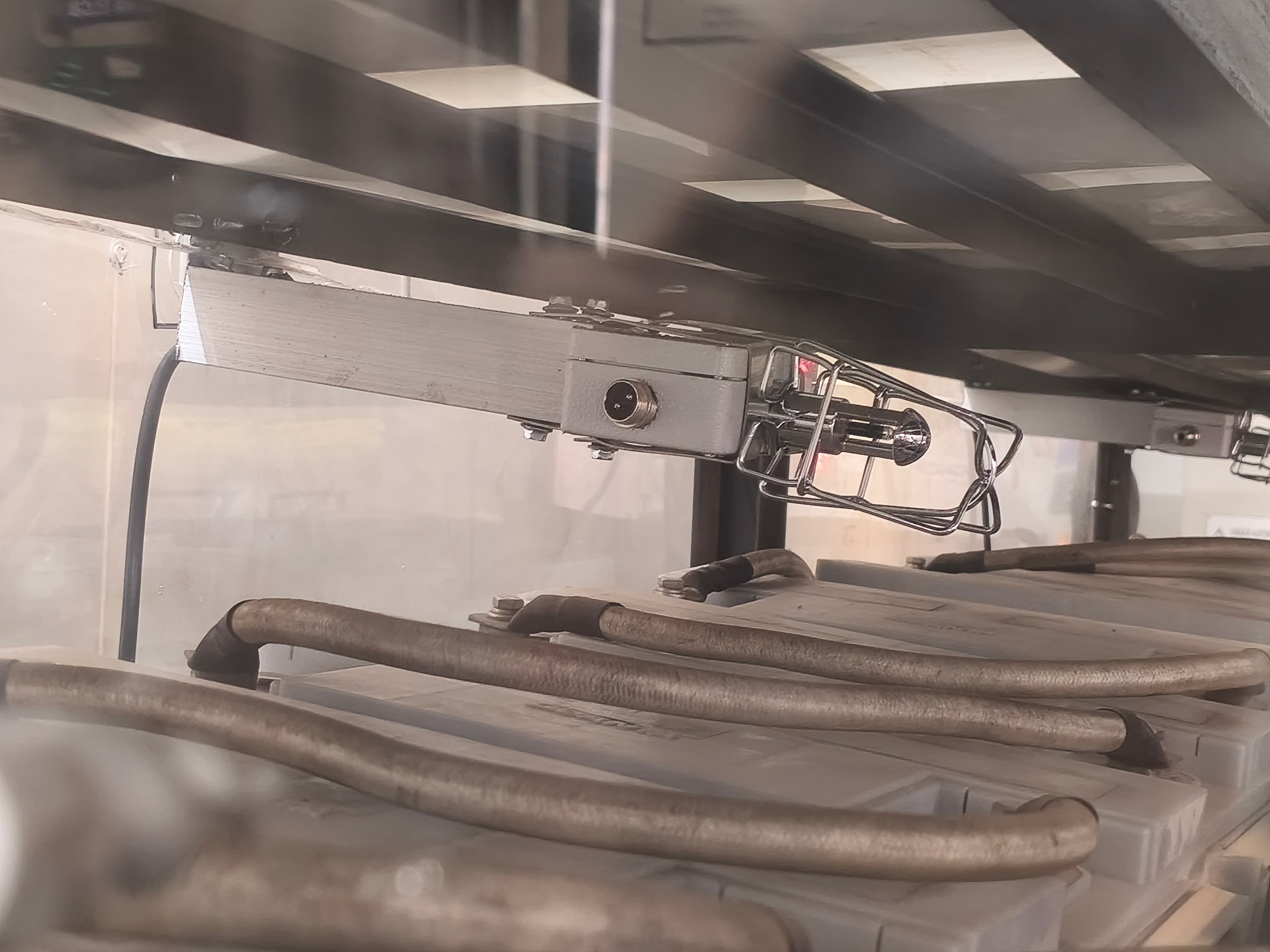
Cinder-built thermal sensor module, five temperature ratings, CE approved.
Range imageSensors
SPDT stainless switch, 0–8 bar, for supervision and discharge signalling.
Range imageSensors
SPDT stainless switch, 0–15 bar, for higher-pressure detection lines.
Range imageSensors
SPST stainless switch, 0–8 bar, single-circuit supervision.
Range imageDetection and supervision devices for suppression and flooding systems: pneumatic heat sensing tube, linear heat sensing cable and the Cinder M.T.S thermal sensor module, conventional smoke and heat detectors, and pressure switches that monitor cylinder charge and signal discharge to the control panel.
Sensors provide different kinds of information to a fire protection system. Heat-sensing tube can be part of a pneumatic suppression arrangement; heat or smoke detectors report a fire condition to compatible controls; pressure switches report a pressure condition. These functions should not be treated as interchangeable. Compare the operating environment, normal temperature, airflow, mounting method and the connection to the control or release equipment. Device placement and commissioning are part of system design. Use this range to identify the appropriate detection approach and supply the equipment layout when requesting a model recommendation or replacement.
No. A pressure switch reports a pressure condition, while smoke and heat detectors sense different fire indicators. Their roles and connections must be defined in the system design.
Normal temperatures, dust, moisture, steam, airflow, vibration and equipment geometry can affect selection and placement. Supply these details with the intended panel or pneumatic system reference.
Tell us about the space you need to protect and an engineer will recommend the right system.
Record normal and exceptional temperatures, dust, moisture, steam, airflow and vibration. Include cleaning or process conditions that could affect the device. A detector that works in a clean room may require a different assessment beside a hot machine or cooking appliance. Do not assume that choosing heat rather than smoke detection removes every environmental problem.
For electrical devices, confirm the compatible panel, voltage, wiring method and input supervision. For sensing tube, confirm the tube specification, fittings and system design. Replacement detectors need to be reviewed against the existing panel, not only compared by their appearance or base size.
Send drawings or photographs showing equipment, obstructions and cable or tube routes. Device spacing, routing and mounting should follow the applicable system design and manufacturer instructions. Ask the installer to identify which equipment and voids are included and how the completed arrangement will be tested.
Keep access to devices and record model references in the equipment schedule. Ask what routine inspection, functional checks and replacement criteria apply to the selected products. Review the arrangement when equipment layouts or operating temperatures change. The electronic-components range shows the related controls and indication devices.